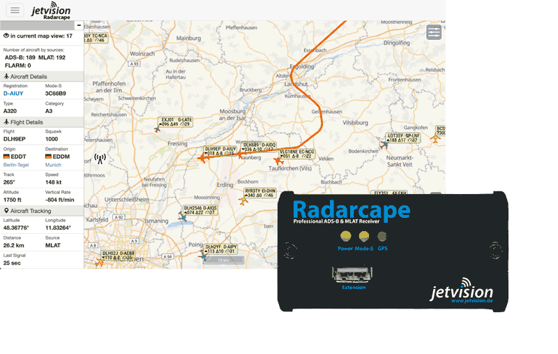


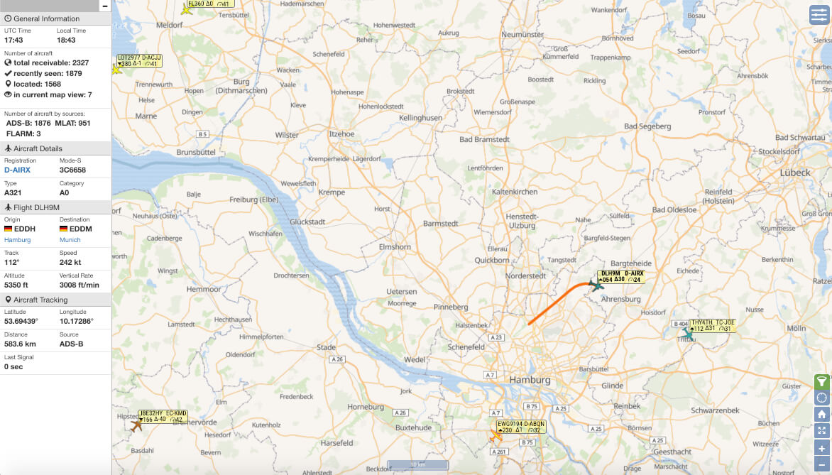
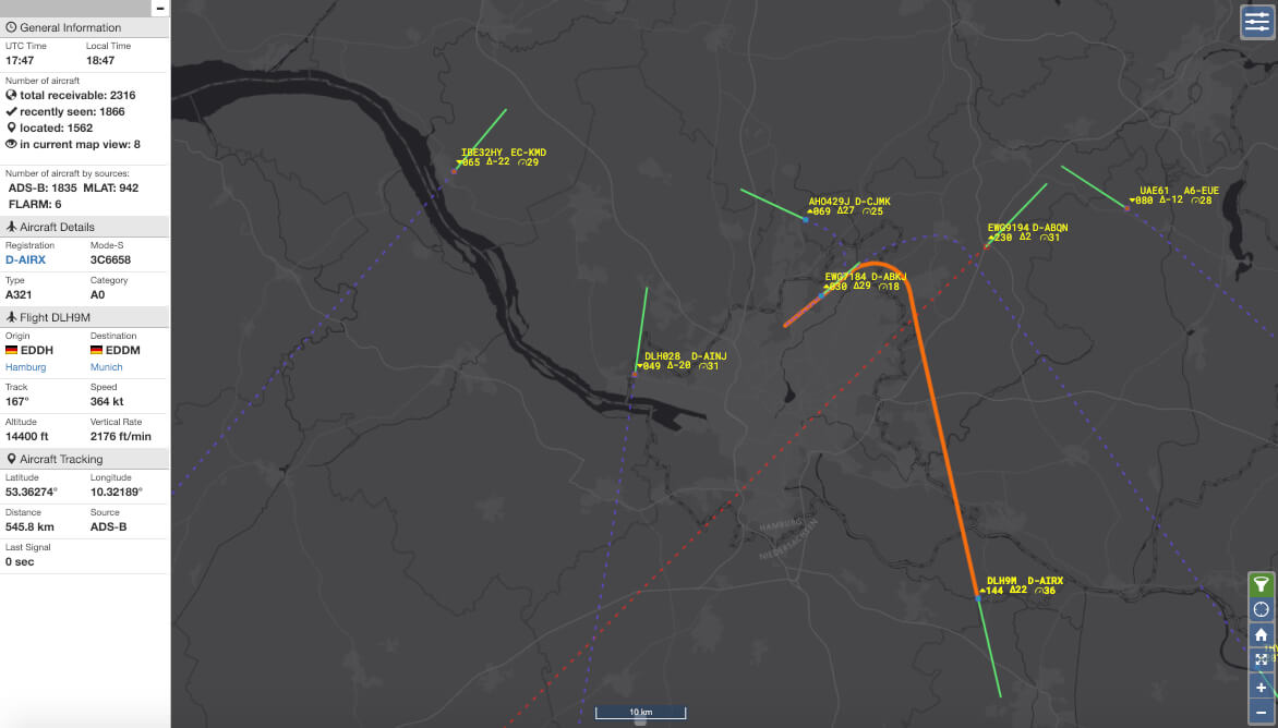
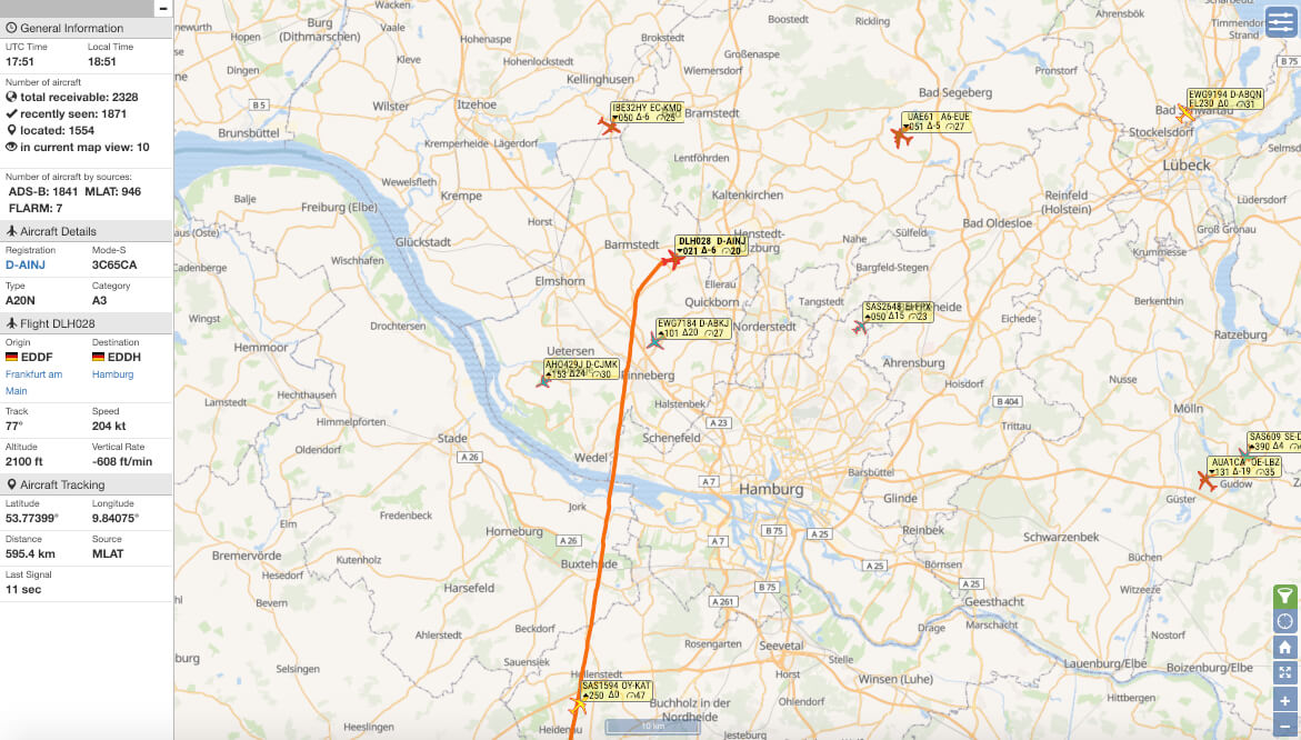
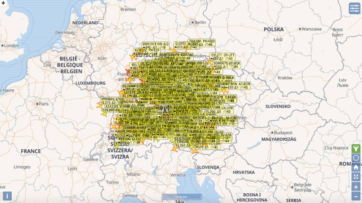
OSM Map (no Overlays)

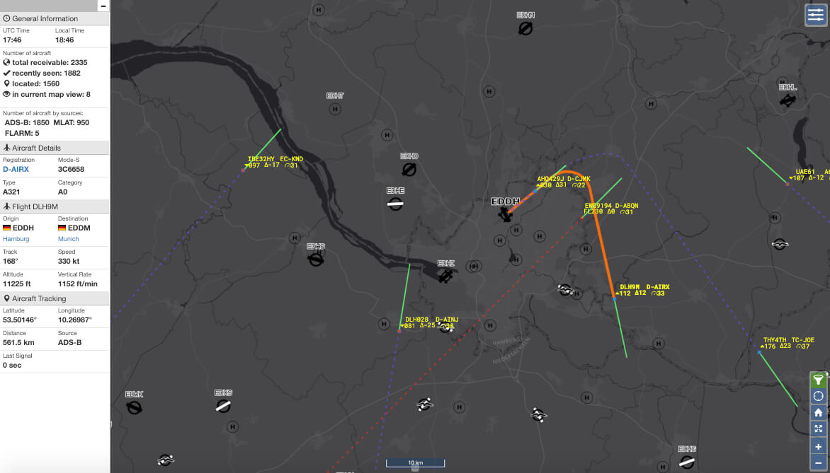
OSM Map - Airports
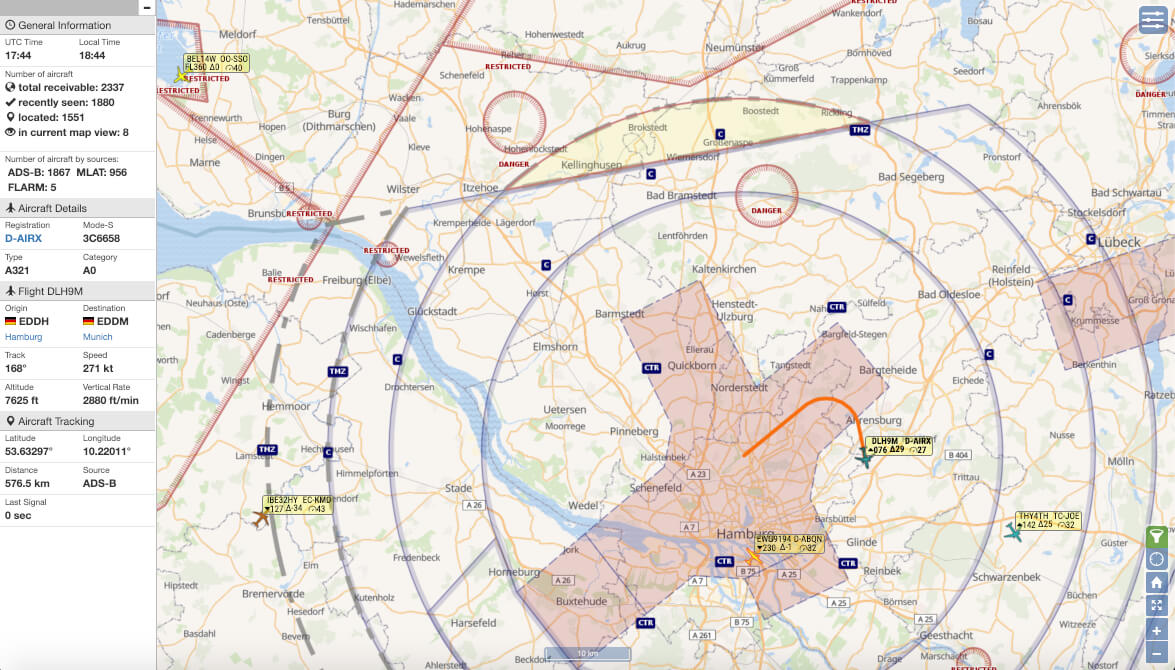
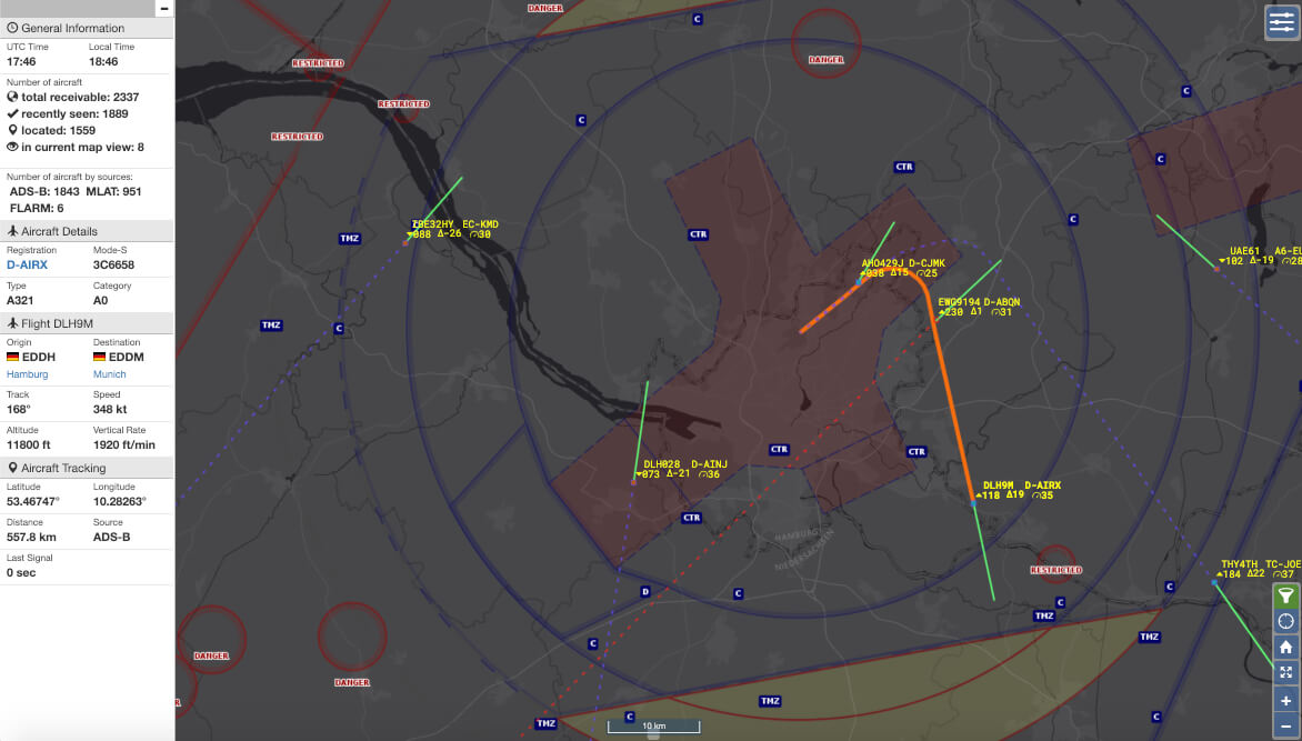
OSM Map - Zones
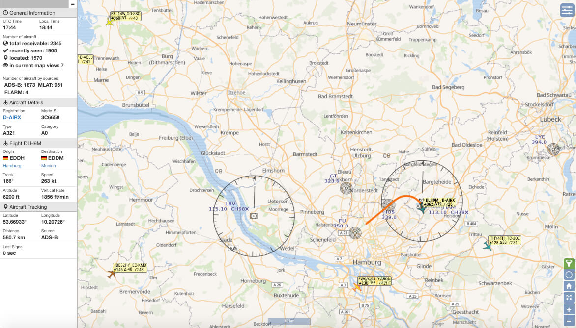
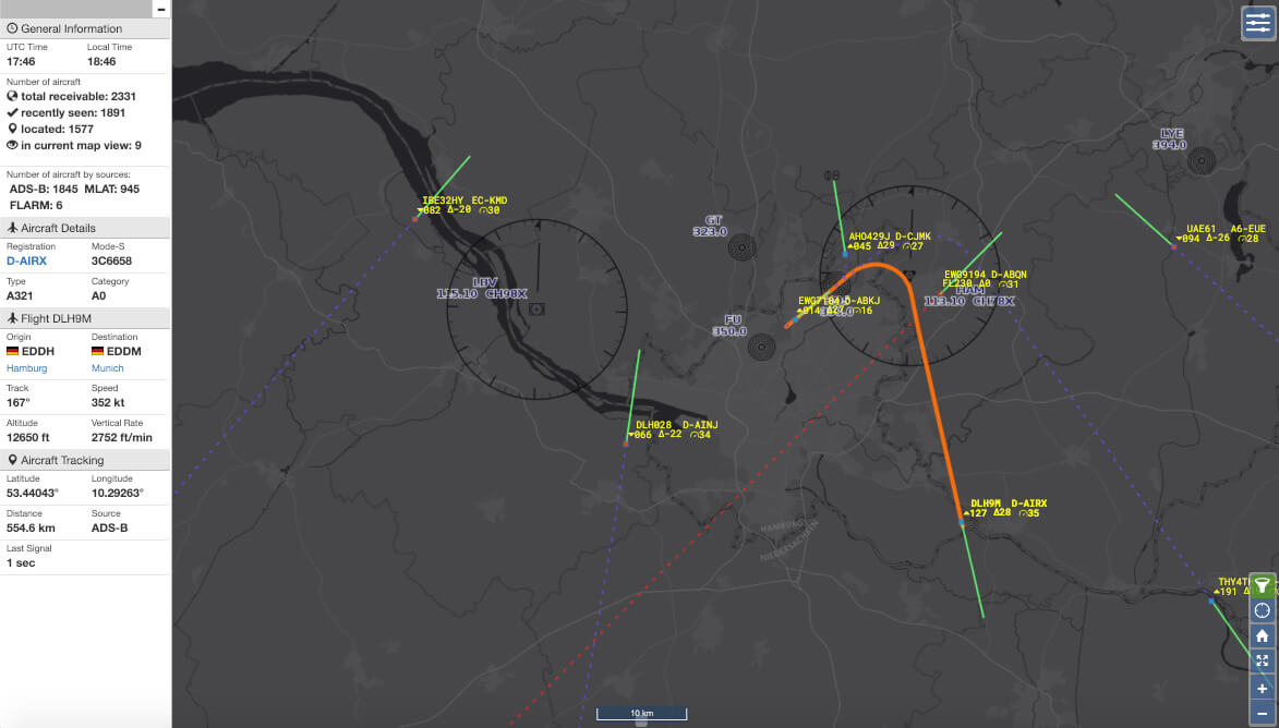
OSM Map - Navaids
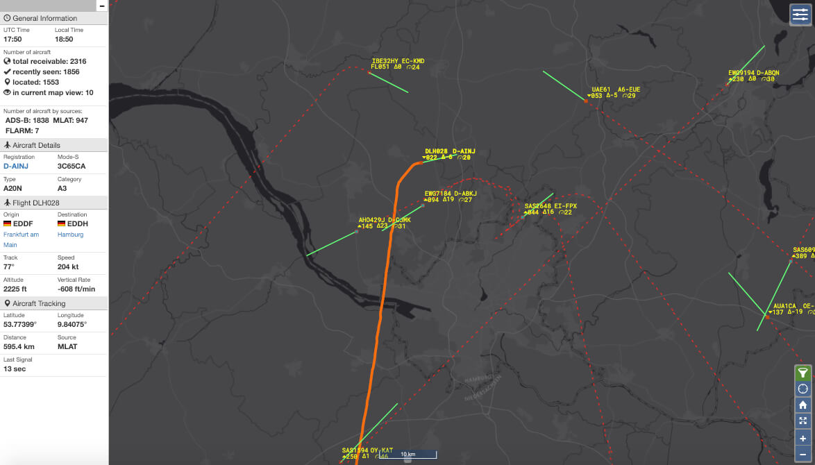
ATC Map - Airports
ATC Map - Zones
ATC Map - Navaids
ATC Map (no Overlays)
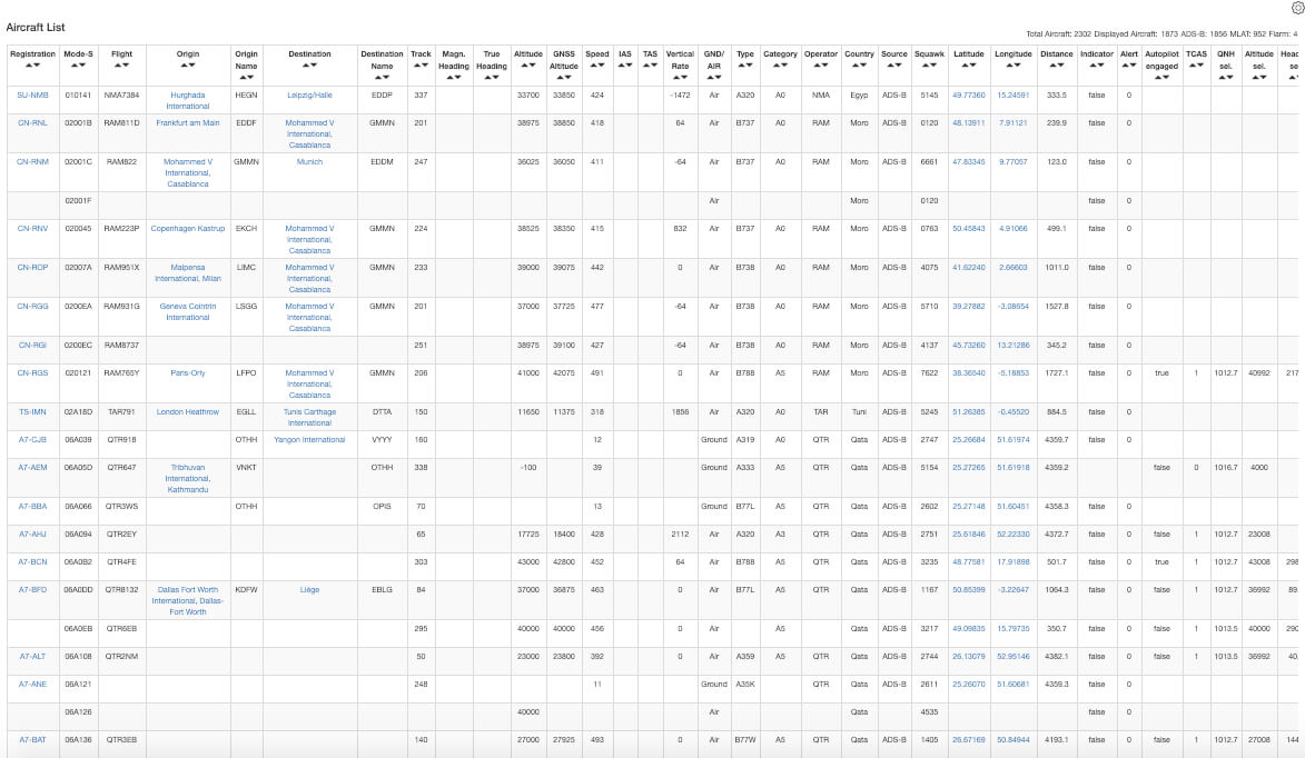
Aircraft List (Detail)
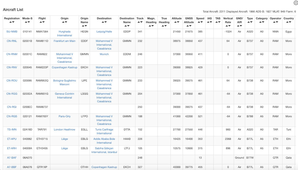
Aircraft List (Overview)
OSM Map - Multilateration (MLAT)
ATC Map - Multilateration (MLAT)
Receiver Range Performance
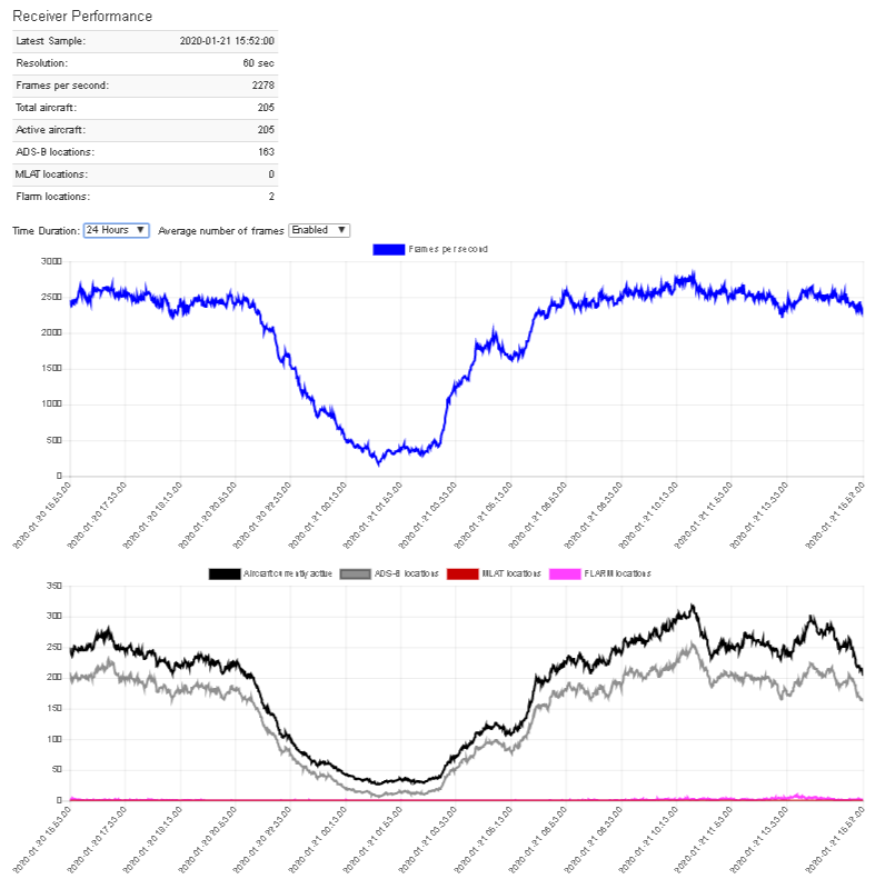
Receiver Performance
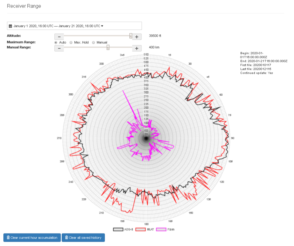
Range Diagram
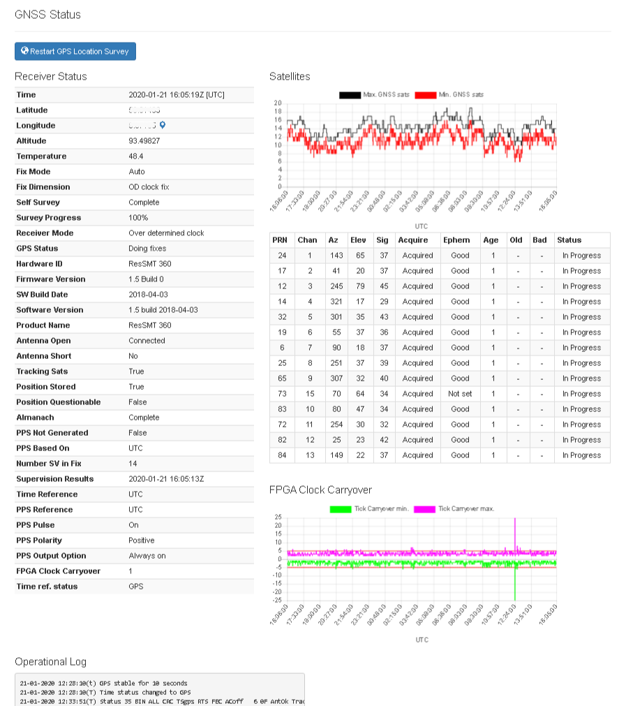
GPS Status
Connected FLARM